EFHW antenna designer
Design an End-Fed Half-Wave (EFHW) or an End-Fed Random-Length (EFRL) antenna, in inverted-L, or inverted-Vee, or sloper form, using a single main support. The EFHW antenna is designed for one principal amateur HF band, usually 80 meters or 40 meters, but typically displays VSWR minima on several higher, harmonically-related, bands and can therefore be a good multi-band antenna. Being an end-fed antenna with a high feed-point impedance and high feed-point voltage, it is used with an unun - typically 49:1, 64:1, or higher - to bring the impedance down to a range which can easily be handled by an antenna matching unit. Read more...
EFHW or EFRL antenna? » » »
-
EFHW - as the name suggests, this is a half-wave antenna (half-wave on the principal band) and so its
length is calculated for you by the program using basic physics;
- this calculation, being based on the principal frequency/band, means that this type is resonant on at least one frequency/band, and can also be resonant on multiple other, harmonically-related frequencies/bands as well;
- the WARC bands are generally NOT well covered;
- the EFHW will present very high impedances, typically around a few thousand ohms, and will be used with a high-ratio unun in the range 49:1, 64:1 or even higher;
- the counterpoise used for the EFHW type will be generally around 0.05 λ (1/20 λ);
- the VSWR curve for an EFHW type will show minima at, or very close to, the frequencies/bands of interest.
-
EFRL - this is an antenna, the length of which is carefully chosen to be
not resonant on any of the frequencies
or bands where it will be used.
- the length chosen should result in an antenna which presents impedances which are in the middle to high hundreds of ohms on bands of interest;
- many bands can be covered, including some WARC bands;
- an unun ratio in the range of 8:1 to 10:1 would be used to transform the antenna's impedance down to approximate that of the coaxial cable;
- the length chosen for the counterpoise can be critical in determining the impedances, especially at higher bands; try a counterpoise length of about 0.1 λ (1/10 λ) ;
-
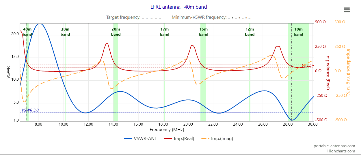
the VSWR curve for an EFRL type is NOT expected to show minima at any frequencies corresponding to
the bands of interest. This example shows the VSWR curve for a typical EFRL sloper of 22 meters (72ft)
length, with a counterpoise of 4.19 meters (0.1 λ), fed via a 9:1 unun :
The VSWR (blue curve) minima are to be ignored here: the important data is in the red and orange curves which, after transformation by a 9;1 unun, show transformed impedances between approximately 50 Ω and 100 Ω on the bands 40m, 20m, 15m and 10m. These values are readily matched by the internal or external antenna tuner used with most EFRL installations
| Length, feet |
Length, meters |
Bands* |
| 29.0 | 8.84 | 30m - 10m |
| 35.5 | 10.82 | 40m - 10m |
| 41.0 | 12.50 | 40m - 10m |
| 52.0 | 15.85 | 60m - 10m |
| 58.0 | 17.68 | 60m - 10m |
| 71.0 | 21.64 | 80m - 10m |
| 107.0 | 32.61 | 80m - 10m |
| 119.0 | 36.27 | 80m - 10m |
| 135.0 | 41.15 | 160m - 10m |
| 148.0 | 45.11 | 160m - 10m |
| 203.0 | 61.87 | 160m - 10m |
| 347.0 | 105.77 | 160m - 10m |
| 407.0 | 124.05 | 160m - 10m |
| 423.0 | 128.93 | 160m - 10m |
|
*
Some bands may not be available
or tunable in your setup |
||
Get started » » »
- Use the controls on the left-hand side to configure your antenna - set the design frequency, antenna element lengths and angles, wire diameter, wire insulation if required, support height, etc.
- When you are happy with your configuration, press the "Show antenna" button to display your antenna in interactive 3D graphics mode in the area on the right-hand side. Each time you change your configuration, you should press the "Show antenna" button to register the changes to the app.
-
After you have configured your antenna, you can then use the controls further down in the page to generate charts and diagrams to evaluate
the antenna's performance - you will need to
scroll down in the page
to access these controls.
You can choose to view any combination of the available charts and diagrams: these include four radiation pattern types: azimuth, elevation, 3D and polarization patterns; other options include VSWR charts, an antenna currents diagram, and a Smith chart.
|
|
Set antenna color: |
||||||||||||||||||||||||||||||||||||||||||||||||||||||||||||||||||||||||||||||||||||||||||||||||||||||||
|
EFHW (End-Fed Half-Wave) antenna designer
portable-antennas.com
Antenna feed-point: ⬥
Inductance load: ●
|
||||||||||||||||||||||||||||||||||||||||||||||||||||||||||||||||||||||||||||||||||||||||||||||||||||||||
Antenna performance
Here you can generate plots of
radiation patterns,
VSWR chart, antenna currents diagram and Smith chart for your antenna over a
choice of ground types. By changing the physical dimensions of the antenna, and refreshing these plots, you can learn a lot about
how such antennas will perform in the field.
Please note that
radiation patterns are here modelled over flat ground -
when the antenna is erected on a hill-top or mountain summit, the surrounding sloping ground will generally cause angles in
the elevation radiation pattern to be lowered in the direction of the
slope: the steeper the slope, the lower the effective elevation take-off angle will be, and the better the chances of making
long-distance contacts.
Read more...
|
Choose ground type of
land in the vicinity of the antenna: |
Conductivity:
S/m
Dielectric const.:
F/m
|
| View radiation patterns: |
|
| Choose type: | |
| Set ref. elevation angle: |
|
| Set ref. azimuth angle: |
|
| Radiation patterns for: |
|
| Impedance transformer: |
unun
|
| View VSWR chart: | Check on: From: To: |
| Effect of coax on VSWR: |
Coax length:
Type:
Effect of coax- and system-losses on VSWR
>>> NOTE: These remarks are not applicable to the EFRL antenna type <<<
When a coaxial cable is used to connect the antenna to a transmitter, the cable introduces signal loss, the magnitude of which can vary strongly with both frequency and antenna feed-point impedance. The main blue VSWR curve for this antenna is calculated at the antenna feed-point. The optional green curve represents the VSWR "seen" at the transmitter after losses in the coaxial cable are taken into account. At frequencies of antenna resonance, the blue and green curves usually coincide closely, since the coax contributes little additional attenuation at those frequencies. At frequencies away from resonance, however — often those corresponding to WARC bands — the feed-point impedance may become highly mismatched, producing very high VSWR values in the blue curve while the green curve shows substantially lower values. This reduction in VSWR at the transmitter occurs because signal losses in the coaxial cable attenuate both the forward and reflected waves. As a result, the reflected signal returning to the transmitter is weaker, causing the transmitter-end VSWR to appear lower than the actual feed-point VSWR. This effect can make some bands appear more "usable" from the transmitter's perspective, even though the antenna system may still be operating inefficiently at those frequencies. The green curve represents the "flattening" of the VSWR caused by the coax. Additional losses elsewhere in the system can further reduce the transmitter-end VSWR - these may include:
The magnitude of such losses, and their effect on actual radiated RF power, can only be estimated reliably through careful analysis of a particular antenna setup. In every-day portable operations, such losses can only be roughly estimated; however, comparisons can be made between commercially-produced EFHW and OCFD antennas for amateur radio use, and carefully-configured NEC models of those same antennas. Useful estimates can then be made of the efficiency of the commercial products by comparing their published VSWR curves, and the VSWR curves produced from the models. The dashed red curve (VSWR-FIELD) represents what might be measured in the field by an antenna analyzer connected to the transmitter end of the coax when this antenna is erected "in the field," i.e. either when operating portable, or at the home QTH. This curve approximates the effect on VSWR of all the sources of signal loss mentioned above, and illustrates how real-world losses can further flatten the measured VSWR, either with a home-brew, or a commercial, EFHW antenna. Improved transmitter-end VSWR therefore does not necessarily imply improved radiation efficiency: in some cases, a significant proportion of the transmitted power may simply be lost: dissipated as heat within the antenna system. Read more... |
| View currents diagram: | |
| View Smith chart: |
|
|
Antenna gains at 0° elevation: |
|
| Feed-point impedance: | |
| Estimated bandwidth: | |
