Extras - Reference data and charts
Reference data for parameters used in this site. Access these via the tab pages below:
Animated standing-wave charts
Animated depiction of forward and reflected waves, and the resultant combined wave, in a lossless feedline between a source (transmitter) and the feed-point at a load (antenna). An impedance mismatch here will result in some of the forward wave being reflected back to the source - the greater the mismatch, the greater will be the amount of reflection, and the greater the magnitude of the reflection coefficient \( \Gamma \).
Use the slider to set the reflection coefficient magnitude - this will have the effect of generating an impedance mismatch between the feedline and the load/antenna in this simulation. This will also affect the values of VSWR, mismatch loss, etc. displayed in the upper row, and also update the chart. The chart displays, instant by instant:
- a forward wave propagated in a feed-line from a source (e.g. a transmitter)
- a wave, reflected back to source along the feed-line, by an impedance mismatch at the load
-
a resultant wave, a combination (by the superposition principle) of the forward and reflected
waves' voltage amplitudes, resulting from the impedance mismatch
This resultant wave will form part of the standing-wave pattern but - except in the case of total reflection of the incident wave at the feed-point - it is not itself stationary. Instead, the resultant waves will proceed in a non-linear fashion, travelling forward in a complex and halting manner, and repeating over successive cycles. The standing wave pattern is built up from many such resultant waves, as will be seen in the second chart below this one.
|
Reflection coefficient magnitude, \( \lvert \Gamma \rvert \) :
|
VSWR:
|
Mismatch loss:
|
Percent loss:
|
Return loss:
|
|
|
1.000 : 1
|
0.000 dB | 0.000 % | 0.000 dB |
| Animation speed: | Animation cycles: |
Standing wave pattern (single full cycle)
This chart shows each of the resultant waves from the upper chart, as they are generated, and superimposed or overlaid on each other, during one full cycle of the simulation. The outer envelope of the figure so obtained constitutes the standing wave pattern in the feed-line.
|
The height of "ripples" in the standing-wave pattern envelope correlates to the reflection coefficient \( \lvert \Gamma \rvert \).
The VSWR, or standing-wave ratio in the feedline, can be calculated as:
\[ VSWR = \frac {1 + \lvert \Gamma \rvert}{1 - \lvert \Gamma \rvert} \]
Referring to Fig.1, the VSWR can also be calculated as the ratio of the maximum and minimum voltage amplitudes:
\[ VSWR = \frac {\lvert V_{\scriptscriptstyle \mathrm{MAX}} \rvert}{\lvert V_{\scriptscriptstyle \mathrm{MIN}} \rvert} \]
A VSWR of 1:1 (corresponding to \( \lvert \Gamma \rvert = 0 \) ) will result in a standing-wave pattern envelope of constant height.
» Try it!
|
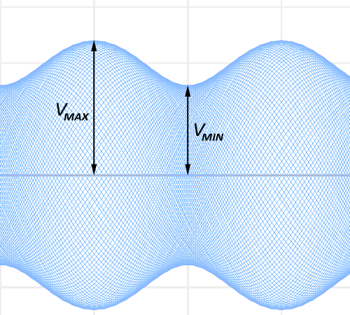
Fig.1 - Example standing wave pattern, maximum
and minimum voltage amplitudes |
The math behind the standing wave patterns
To an engineer, a wave can be represented in complex exponential form as:
where \( \omega = 2\pi f \) and \( k = \dfrac{2\pi}{\lambda} \), where \( \lambda \) is the wavelength.
The two parts \( \omega t \) and \( kx \) in the exponent each play a different and separate rôle in describing such a standing wave. The \( \omega t \) part encodes how the wave oscillates in time, and the \( kx \) part encodes how the wave extends over space.
So, a forward-travelling wave could be represented as \( e^{j(\omega t-kx)} \) and a wave in the opposite direction as \( e^{j(\omega t+kx)} \)
Combining two such waves, and using a reflection coefficient Γ for the second wave:
Taking the real components of the forward and reflected wave, we can express their separate voltage amplitudes in cosine form:
Combining these two waves, forward and reflected, we have (using standard identities):
In this form, the time- and spatial-components are separated out, but act in tandem, such that the quickly time-varying component (the \( \cos(\omega t) \)) is constrained by the stationary spatial component (the \( \cos(kx) \)), which represents the outer envelope when plotted in a X-Y graph, as in Fig.1 above.
Those with a sharp eye will observe that the standing wave's stationary envelope appears to have a frequency twice that (or wavelength half that) of the forward and reflected waves. This is indeed the case: the time part of the combined waves, the \( \cos(\omega t) \) part, has the same frequency as both waves (as would be expected), but the spatial part, the \( \cos(kx) \) part, has
so that
which has maxima at
The forward and reflected waves, however, have maxima at