Support, information and help
Find information on each of the various antenna types currently offered by the portable-antennas.com site.
Antenna types
Currently, the site offers tools to help the user design nine main types of antenna. Click on a link to open a short article describing the chosen antenna type and its' main characteristics:
- Linked dipole antennas - inverted-vee wire antennas for up to six bands
-
OCFD antennas
- wire dipole antennas fed off-center, set up as a half-wave inverted-V, and built for one principal band but, depending on
how the antenna is configured, can be usable on up to four higher amateur bands -
EFHW antennas
- wire antennas fed at one end, set up as a half-wave inverted-L or inverted-V, built for one principal band, but usable on
several higher amateur bands - Vertical antennas - wire antennas built for a single band, set vertically and - depending on the type - with configurable radials or a counterpoise
- Delta loop antennas - wire antennas built for one band only, but well suited to DX work
- Half-square antennas - wire antennas which can be configured either as current-fed full-wave single-banders, or as voltage-fed EFHW multi-banders
-
Moxon antennas
- made of wire or tube, the Moxon is a compact form of a 2-element Yagi with folded elements, most often designed
for a single
band, and with good forward gain and very good front-to-back F/B ratio
and these two "specials":
-
"4DX" Dipoles beam
- a directional wire beam antenna, consisting of an array of two angled inverted-vee dipoles (or linked dipoles),
and which can
very quickly be made to radiate in any one of four different directions -
Hentenna antenna
- a rectangular asymmetrical double-loop beam antenna, designed for a single band, with good side rejection and
low elevation
angle - a good DX antenna
Extras
The site also offers collections of charts, tables, calculators and reference material in these three Extras pages:
-
Extras - coax data and charts
- data-sets and charts for over 20 coaxial cable types suitable for portable operations
- a chart of additional line losses due to SWR
- a chart of SWR at the transmitter plotted against SWR at the antenna, for various loss figures
- a discussion on how we calculate losses, due to a transmission line, in VSWR charts
-
Extras - calculators
- a frequency to wavelength calculator
- a calculator to convert a VSWR value to mismatch loss, percentage power lost, etc.
- a Metric to Imperial units calculator
- a calculator to convert reactance value to inductance or capacitance value
- a calculator to add or subtract decibel values
- a calculator to find the matching impedance of a quarter-wave line matching transformer
-
a table to aid in estimating the amount by which the length of a newly-constructed wire antenna
should be adjusted, in order to achieve resonance at the design frequency
-
Extras - reference
- tables and charts of reference correction factors
- charts of length-correction factors for various types and/or thicknesses of wire insulation
About the designers
Each of the designers listed here share a common structure and form, while presenting combinations of controls specific to the type of antenna covered.
In each case, the user is presented with a group of controls in the upper left portion of the page: these controls enable the user to completely specify the characteristics of the antenna, namely frequency, wire lengths, angles, and so on. Please note that all length dimensions are given, or calculated, in meters.
In the upper right portion of the page is a graphics area where the modelled antenna is presented in a 3D context. The graphic can be zoomed, panned and rotated. Antenna feed-points are shown as colored markers; the user may also choose to toggle the appearance of a semi-transparent plane at the height (1.85 meters) of an average person, in order to gain some perspective on how large the antenna would be when erected.
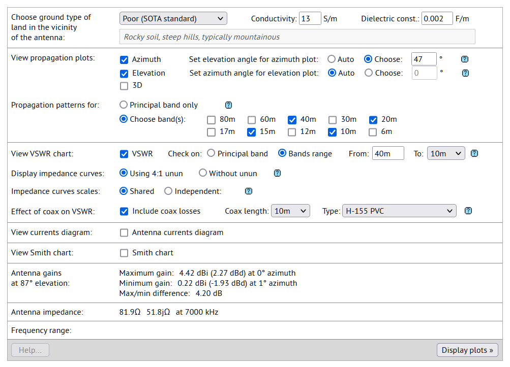
In the lower half of each of the designers, a group of controls enable the calculation of an antenna's performance, and the presentation of charts and diagrams showing the performance in various ways, in any combination of the following:
- azimuth, elevation, 3D and polarization radiation charts
- VSWR charts, incorporating Real- and Imaginary-reactance curves
- an antenna currents diagram
- a Smith chart
Calculation of an antenna's performance is achieved using a NEC4.2 (Numerical Electromagnetics Code v4.2) code-base licensed to the site. Results of the calculations, and the resulting charts and diagrams, are entirely comparable with those presented by programs such as EZNec and 4nec2, for similar antennas. Nonetheless, NO claims are made concerning the accuracy of such information or results; the graphics and data presented in this site are provided "as-is" for the general interest and edification of the user. Refer to this site's Disclaimer for more information.
Linked dipole designer
The linked dipole antenna designer page enables the user to very quickly design a multi-band linked dipole antenna for portable use in the field, or on a mountain top.
This type of antenna is constructed with one or more sections in series, each for a particular amateur radio band, and which are capable of being linked, or unlinked, as required, to make the antenna resonant on whichever band the radio operator wishes to use. Linking or unlinking sections has, however, the downside of having to lower the antenna to physically reach the very highest links.
The links used to join, or separate, individual sections can come in many different forms according to taste, convenience or budget:
- bullet connectors: 2mm or 4mm diameter, gold-plated, soldered or crimped
- banana connectors
- spade connectors, soldered or crimped
- Powerpole® connectors
You'll probably try one or more of these before settling on the one you prefer.
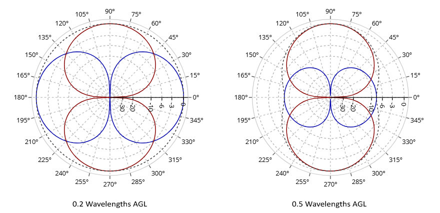
Linked dipole antennas are especially easy to erect, requiring just one support in the center - this could be a pole or a cord suspended from a tree - amd have the added benefit of giving good results even when erected in thick forest. This is due to the fact that, since the antenna radiates predominantly horizontally polarized waves along the main azimuthal lobe*, the trees present little obstacle since they are not only physically, but also electrically vertical. Hence, the trees have little influence on the radiated signals - good for mountain summits, or other portable locations, which are heavily forested.
* Caveat: This is generally true for dipoles at heights AGL of about 0.3 wavelengths or more; for heights lower than this, the vertical component in the polarization pattern (in directions perpendicular to the antenna's main lobes, i.e. in the plane of the antenna) becomes rather larger:
OCFD antenna designer
The OCFD antenna designer page enables the user to quickly design a multi-band OCFD (off-center-fed dipole) antenna for portable use in the field, or on a mountain top. OCFD antennas consist basically of two wires, together comprising one half-wavelength in length, and fed in a similar manner to a center-fed dipole, but fed off-center at a point usually about 1/3 in length from the end; the designer, however, allows the feed-point position to be configured for optimal performance for those bands of interest to the operator.
The OCFD antenna is often stated to present an impedance of around 200 ohms to 250 ohms at the feed-point, and is often fed through an unun, usually 4:1, to match a 50-ohm system. A current choke is often also needed to suppress common-mode currents on the feed-line. However, the actual impedance values of a particular OCFD antenna configuration will most often be quite different, and will vary with:
- the relative antenna section lengths (i.e. as in the most-often used 33% / 67% OCFD),
- the height of the antenna above ground,
- the angles to horizontal of the antenna sections.
Actual values for the impedance at the antenna base frequency can vary between 73 ohms to several hundred ohms, depending on the configuration (refer to the 4th column in the table below).
One big advantage of the OCFD antenna, as compared to a center-fed dipole, is that it can exhibit low VSWR minima on two, three or four higher bands above the principal band for which it has been designed: for example, with a judicious choice of feed-point position, a 40-meter OCFD can resonate also on the 20-meter, 15-meter and 10-meter bands, with the 6-meter band being an added possibility.
The performance of an OCFD antenna is very sensitive to the choice of feed-point position, as the table below demonstrates. This table lists VSWR values at the stated frequencies across several bands for a 40-meter OCFD, principal frequency 7.000 MHz, erected as a flat-top at 10 meters above average ground. VSWR values for the stated frequencies in each band are displayed as a function of the percentage split between the two separate sections of the antenna, here listed as "Left" and "Right":
| Split | Ratio, R/L |
Feed-point impedance at 7.1 MHz |
Band | Bands* | |||||||
|---|---|---|---|---|---|---|---|---|---|---|---|
| Left % |
Right % |
40m (7.1 MHz) |
30m (10.1 MHz) |
20m (14.2 MHz) |
17m (18.1 MHz) |
15m (21.2 MHz) |
12m (24.9 MHz) |
10m (28.5 MHz) |
|||
The animation below uses the same antenna configurations as the table, and demonstrates graphically how sensitive an OCFD antenna is to the relative ratios of the two sections, left and right:
| 40-meter OCFD antenna |
From these data, it can be seen that the most often-used 1/3 to 2/3 (or 33% / 67%) ratio section lengths used for a 40-meter OCFD antenna will result in the antenna being resonant on three amateur bands, 40m, 20m and 10m, but NOT on 15m. In order to get a 40-meter OCFD antenna to be resonant also on the 15m band, a different lengths ratio between the antenna sections must be used.
Among the best ratios to be used, as both the graphic and the table show, are close to an 18% / 82% or 20% / 80% ratio which gives good
VSWR minima on all four bands 40m, 20m, 15m and 10m. This is also borne out by the comments made in Part 4 of this document on OCFD antennas:
https://rsars.files.wordpress.com/2013/01/study-of-the-ocf-dipole-antenna-g8ode-iss-1-31.pdf
where the author suggests a 1/6 to 5/6 (or 16.67% / 83.33%) ratio would be the best choice to bring the antenna to resonate on four HF bands
40m, 20m, 15m and 10m, and incidentally also on the 6-meter band.
Changing the angles (within reasonable limits) of the two arms of an OCFD antenna has a much less profound effect on VSWR and bands coverage than the choice of feed-point position. Angling one or both arms downward, however, has the effect of lowering the antenna impedance somewhat.
The OCFD antenna can be a very useful and time-saving field antenna in the field - simply change TRX band to one of the antenna's resonant bands, and start transmitting.
EFHW antenna designer
The EFHW antenna designer page enables the user to quickly design a multi-band EFHW (end-fed half-wave) antenna for portable use in the field, or on a mountain top. EFHW antennas consist basically of one single wire, a half-wavelength in length, which can be configured in several ways:
- as an inverted-L antenna
- as an inverted-V antenna
- as a vertical antenna
Being end-fed, the EFHW is voltage-fed and presents a high impedance (around 2500 ohms to 3500 ohms) at the feed-point, and hence needs an unun, typically 49:1, to match a 50-ohm system.
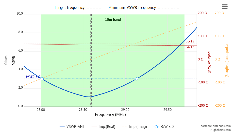
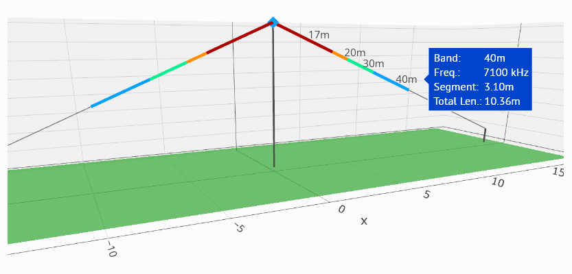
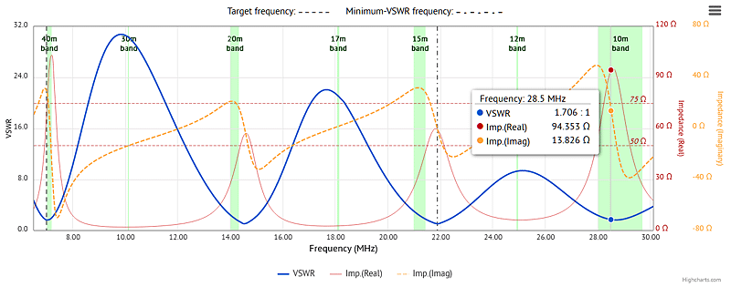
One big advantage of the EFHW antenna is that it can exhibit low VSWR minima on several bands above the principal band for which it has been designed: for example, a 40-meter EFHW can resonate also on the 20-meter, 15-meter and 10-meter bands, with 6-meters being thrown in for good measure. This can readily be seen in the diagram below:
Careful optimization of the EFHW antenna characteristics is needed to ensure good performance in the field. Ground conductivity plays a part, as well as choice of principal frequency, configuration, and inductive/capacitive loading of the antenna. If done right the EFHW antenna can be a very useful and time-saving field antenna - simply change TRX band to one of the antenna's resonant bands, and start transmitting.
Vertical antenna designer
The Vertical antenna designer page enables the user to quickly design a single-band vertical antenna for portable use in the field, or on a mountain top. For portable use, the vertical antenna is most often constructed of wire, supported by a pole of sufficient height to accommodate the complete antenna length.
The designer covers three major variants of the type, for HF and for VHF/UHF:
- 1/4-wave vertical, with configurable radials
- 1/2-wave vertical, with configurable counterpoise
- 5/8-wave vertical, with configurable radials
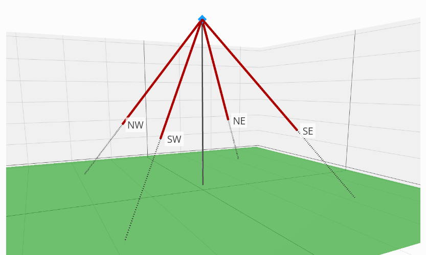
When configured as a 1/4-wave or 5/8-wave vertical, a set of radials are required to "complete" the antenna. How many radials, of what length, and at what downwards slope angle they should be arranged: these are matters for the builder to decide.
The designer allows the user to set the number of radials, their lengths and slope angle. A minimum of one radial can be enough to "get a signal out" while operating portable, but at the cost of skewing the radiation patterns; however, 3 or 4 radials equally spaced will give excellent results. Some portable operators use eight or more radials, but it has to be said that the "law of diminishing returns" is at work here - many more radials does not necessarily translate to much better performance.
When configured as a 1/2-wave vertical, however, the antenna does not need radials, although they can be used if desired, and is essentially an end-fed half-wave (EFHW) antenna. As with all such EFHW antennas, a counterpoise is often used, and is recommended, at the feed-point. This counterpoise ideally has a length which optimizes the feed-point impedance: in particular, a length is chosen which brings the reactive component of the impedance as close to zero as possible. Most observers agree that the optimum counterpoise length is 1/20 λ (0.05 λ).
1/4-wave vertical, with configurable radials
The 1/4-wave vertical is perhaps the best-known of the vertical antenna variants. The main radiating element is shorter than the others covered here, and the total length of the antenna can often easily be laid along a non-conducting support, such as a fiberglass pole.
This makes it a good single-band DX antenna.
If erected higher than about 1/4-wavelength above the ground, the elevation radiation pattern begins to show additional lobes at higher elevation angles, thus increasing the chances of making contacts at shorter distances.

As noted above, the user can choose any number of radials from one single radial, up to a maximum of ten radials - enough for even the most demanding of portable operators. The radials' angle can also be set between 0° for radials laying along the ground, up to a maximum of 50°. Altering the radials' angle will affect the feed-point impedance: an angle of 45° will result in an impedance close to 50 Ω. A chart of feed-point impedance plotted against radials angle will be found in the Reference dialog in the Vertical Antenna designer page.
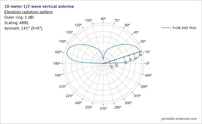
1/2-wave vertical, with configurable counterpoise
The 1/2-wave vertical antenna is basically a single element end-fed half-wave (EFHW) antenna vertically arranged. Like all EFHW antennas, the 1/2-wave vertical has a very high feed-point impedance - on the order of 1500 Ω to 2500 Ω - and therefore requires a matching device to transform this high impedance to one close to 50 Ω.
The low elevation angle makes it a good antenna for long-distance DX operation.
If erected higher above the ground, the elevation radiation pattern begins to show additional lobes at higher elevation angles, thus increasing the chances of making contacts at shorter distances.
In addition, it is found that the addition of a short counterpoise of a certain length at the feed-point will help to reduce the reactive component of the high feed-point impedance to close to zero. The optimum length of such a counterpoise has been found by many observers to be 1/20 λ (0.05 λ). A chart of feed-point impedance plotted against counterpoise length will be found in the Reference dialog in the Vertical Antenna designer page: the optimum length can be readily ascertained from the chart.
As an example, the optimum counterpoise length for a 10-meter 1/2-wave vertical antenna is found to be close to 0.5 meter - rather short when compared to the 5 meters length of the main vertical element.
The counterpoise itself can be either:
- a separate length of wire of the correct length, attached at the antenna feed-point: in this case, a current choke is need on the coax at the feedpoint;
- the coax cable itself, with a current choke at a length from the feed-point equal to the optimum counterpoise length: in this case, the length of the coax sheath from feed-point to choke acts as the counterpoise.
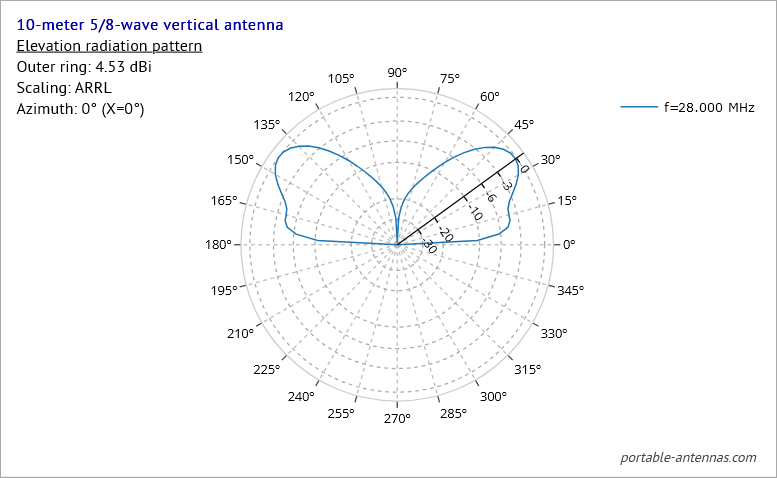
5/8-wave vertical, with configurable radials
In most respects, the 5/8-wave vertical antenna has characteristics closely resembling those of the 1/4-wave vertical, but differs in the shape of the elevation radiation pattern.
This higher elevation angle makes it a good antenna for middle distances and shorter skip lengths than the 1/4-wave vertical.
If erected higher than about 1/4-wavelength above the ground, the elevation radiation pattern begins to show additional lobes at even higher elevation angles, thus increasing the chances of making contacts at shorter distances.
Delta loop antenna designer
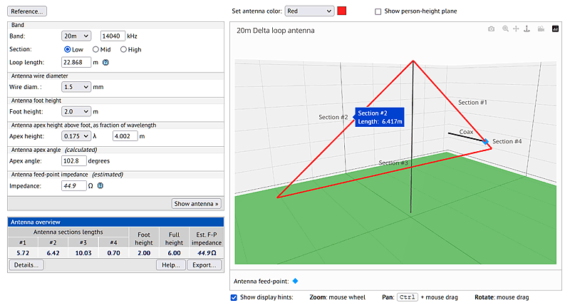
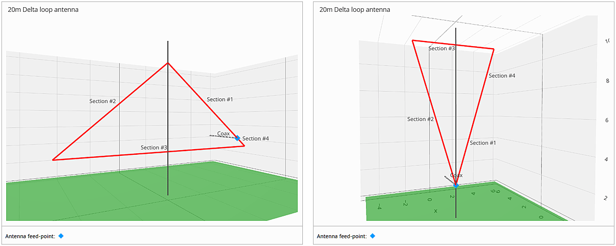
The delta loop designer page enables the user to quickly design a single-band triangular delta loop antenna for portable use in the field, or on a mountain top. In its' "apex-up" configuration, the antenna needs just one support, either a pole or a cord suspended from a tree. The "point-down" configuration, on the other hand, requires two such supports.
This type of antenna is constructed as a closed triangular loop, with the apex either at the top of the loop ("apex-up"), or at the bottom of the loop ("apex-down"). The shape of the triangular loop depends strongly on the main configuration, "apex-up" or "apex-down" - in order to keep the feed-point impedance close to 50Ω in each case, the "apex-up" variant needs to be much shallower and broader than the "apex-down" variant, which is narrower and taller, as the graphic makes clear:
The user can choose any of the following allowed configurations and feed-point positions in the loop (the options highlighted are not recommended, or not available);
| Feed-point position | Polarization direction | |
|---|---|---|
| Apex-up configuration | Apex-down configuration | |
| At the apex | Mixed polarization (NVIS) | Horizontal polarization* |
| At a point 1/4 wavelength down from the apex | Vertical polarization* | N/A |
| At one corner of the horizontal section | Vertical polarization | Mostly horizontal polarization |
| At the mid-point of the horizontal section | Mixed polarization (NVIS) | Horizontal polarization |
The table shows that the delta-loop antenna in the "apex-up" configuration exhibits either vertical polarization or mixed horizontal/vertical polarization, depending on the position of the feed-point in the loop. In the "apex-down" configuration, on the other hand, the polarization direction is predominantly horizontal.
NOTE: When the feed-point is positioned at 1/4 wavelength down from the upper apex point, it is important to note that the coaxial cable inner conductor is attached to the 1/4-wave section, and the coax shield is attached to the other short section on that side.
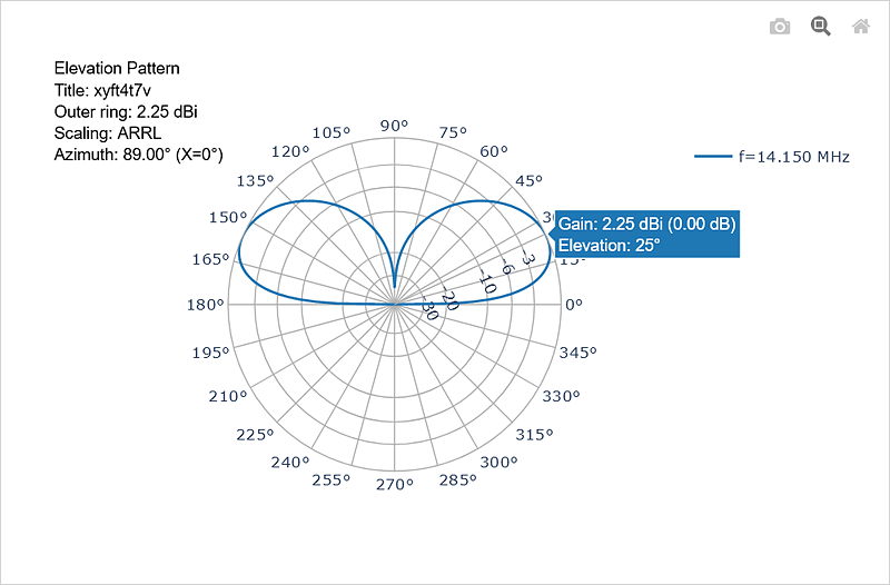
The delta-loop antenna generally features a low vertical take-off angle, even though such antennas are erected with either their lower side (in "apex-up" configuration) or their apex point (in "apex-down" configuration) only a couple of meters above the ground. The low take-off angle makes this kind of antenna a worthwhile prospect for DX-ing, especially while operating portable. If erected on a summit where the ground drops away appreciably from the summit, the take-off angle will be even lower; placing the delta-loop antenna higher up on its' center support will also lower the take-off angle.
Another feature of the delta-loop azimuthal radiation is the deep, or even very deep, low at high elevation angles (see the diagram below), meaning much less power is dissipated at high angles. This means, however, that this antenna is not a good choice for NVIS communications.
The delta-loop antenna is also fairly broadband on its' designated band - the 2.0:1 VSWR range on the 20-meter band for example, at ~350kHz wide, covers the entire band.
Two slight disadvantages can be encountered when erecting the delta-loop antenna:
- it requires a little more effort to erect than a dipole or OCFD or EFHW antenna
-
the coax feed-line needs to be carefully led away from the antenna at 90° for a couple of meters, in order to minimize common-
mode
currents on the coax sheath.
One should also note that the antenna will exhibit high voltage points, the placement of which are dependent on the configuration and feed-point position: the user should check the currents diagram for points at which the current is low, and the voltage therefore high. The antenna should be erected high enough (2 meters minimum) that neither the operator nor a casual passer-by can easily come into contact with any such high voltage point(s).
Half-square antenna designer
The half-square antenna designer page enables the user to quickly design a half-square antenna for portable use in the field, or on a mountain top. This type of antenna needs two supports: a combination of pole(s) and/or cord(s) suspended from a tree. Half-square antennas can be configured in one of two ways:
- when fed from one of the top corners, it functions as a full-wave single-bander
- when fed from one of the ends, it functions as an EFHW half-wave multi-bander
Half-square antenna configured as a full-wave single-bander
When configured as a full-wave single-bander, the impedance at the upper corner feed-point is approximately 50 ohms, and hence does not necessarily need an unun at the feed-point, although a 1:1 unun is often used. It's important to run the coax feed-line at 90° to the antenna for a couple of meters in order to minimize common-mode currents on the coax sheath.
This configuration results in a fairly low angle (~ 20° to 25°) elevation radiation pattern, with good broadside lobes, deep (typically better than 12dB) rejection in the plane of the antenna, and a deep (~15dB) minimum at high elevation angles. This makes this configuration a good choice for single-band DX work.
Half-square antenna configured as an EFHW half-wave multi-bander
When configured as a half-wave multi-bander, the impedance at the end of the wire is around 2500 ohms to 3500 ohms, and hence an unun, typically 49:1, is needed at the feed-point. In addition, the antenna will most often need a short (~1/20 wavelength) counterpoise to bring the reactive component of the impedance to as close to zero as is practicable.
Like other EFHW antennas, this configuration can exhibit low VSWR minima on several bands above the principal band for which it has been designed: for example, a 40-meter half-square configured in this way can resonate also on the 20-meter, 15-meter and 10-meter bands, with 6-meters being thrown in for good measure.
Moxon antenna designer
The Moxon antenna designer page enables the user to quickly design a Moxon 2-element beam antenna for portable use in the field, or on a mountain top. This type of antenna needs a single support only.
First designed in the early 1950's, and later further developed by L.B.Cebik in the 1980's, the Moxon antenna has become a firm favourite for those interested in building a lightweight beam antenna for home or portable use.
Since the Moxon is a beam antenna consisting of a driver element and a single parasitic reflector element, both folded toward each other, it makes for a usefully compact array. It can be made of wire supported by spreaders, or from lightweight tube which is mostly self-supporting. In both cases, however, a single support only is needed, which is very handy when erecting the antenna for portable operations.
Moxon antenna gain
Like other beam-type antennas, the Moxon can be configured either as a horizontal beam, or as a vertical beam, with the radiation polarized as the configuration. The gain to be expected from the horizontal Moxon is quite high, at 10dBi or greater; the vertical Moxon, on the other hand, exhibits rather lower gain, at about 5 dBi or 6 dBi, depending on height AGL.
In either configuration, as with all 2-element driver-reflector beams, the gain is highest at the low end of the band and tapers off as the frequency is increased. See the following sections for more information...
Moxon antenna configured as a horizontal beam
The horizontal Moxon beam offers a broad forward azimuthal radiation lobe giving modest directivity of about 2dB, with a deep null toward the back end, giving a high front-to-back ratio: gains of up to 9.7dBi are possible. The azimuthal radiation pattern is only moderately sensitive to the height of the antenna above ground, whereas the shape of the elevation pattern depends very strongly on the height of the antenna above ground. The following animation shows both azimuth and elevation patterns for a horizontal 10-meter Moxon beam at heights between 4m and 10m above ground level (height measured at the antenna center):
| Horizontal Moxon |
As can be seen from the graphic, at lower heights of 4m or 5m AGL, the elevation pattern consist of a single lobe with elevation angle of around 25° to 35°. At greater heights AGL, the elevation pattern splits into two very distinct lobes, one low and one high, such that the signal is "shared" between them - this can be useful for both long-distance DX contacts, as well as for more close-in contacts.
Moxon antenna configured as a vertical beam
The vertical Moxon beam offers a very broad forward cardioid azimuthal radiation lobe giving modest directivity, with a deep null toward the back end, giving a high front-to-back ratio. Both the front-to-back ratio and the SWR depart from optimal values more rapidly below the design frequency than above it. Hence, the design frequency will normally be about 1/3 the way up the overall operating passband.
The azimuthal radiation pattern exhibited by the vertical Moxon beam is only moderately sensitive to the height of the antenna above ground, whereas the shape of the elevation pattern again depends very strongly on the height of the antenna above ground.
The following animation shows both azimuth and elevation patterns for a vertical 10-meter Moxon beam at heights between 1m and 8m above ground level (height measured at the lowest part of the antenna):
| Vertical Moxon |
As with the horizontally-oriented Moxon, the elevation pattern at different heights AGL also shows a second elevation lobe above the main lobe, but at shallower angles than with the horizontally-oriented Moxon. At lower heights of 1m or 2m AGL (measured at the lowest part of the vertically-oriented antenna), the elevation pattern mainly consists of a single lobe with elevation angle of around 15°.
At greater heights AGL, the elevation pattern splits into two lobes, one at low elevation and one at a somewhat higher elevation, such that the signal is "shared" between them, but in this case, the two elevation pattern lobes are much closer together than is the case with the horizontally-oriented Moxon, and present more of a low- to mid-angle "broad front", serving both DX and middle-distance contacts.
Moxon antenna VSWR curve
The Moxon antenna has a very distinctive and asymmetrical VSWR curve, the shape of which is only weakly dependent on orientation and/or height AGL:
The curve displays a steep rise at frequencies below the VSWR minimum, and a more shallow rise at frequencies above the VSWR minimum.
In all cases, and using the calculated dimensions, the feed-point impedance stays close to 50 Ω, the VSWR is low (2.5 or less)
and bandwidth is high - even across such wide bands as 10 meters, 6 meters and 2 meters.
"4DX" Dipoles beam antenna designer
The "4DX" Dipoles beam antenna designer page enables the user to quickly design a switchable 2-element wire beam antenna for portable use in the field; this type of antenna needs a single support only. This type of antenna is something of an "outlier" in terms of portability, since its' footprint size would probably be too large for most quick mountain-top deployments. Nonetheless, it would make an excellent choice for activations of parks, or islands/lighthouses, or for Field Day.
The antenna consists of four separate sloping wires making up an array of two angled inverted-vee dipoles, the apexes of which are arranged very close to each other at the center. Each half of the array is a full-sized single-band dipole, or multiband linked dipole, antenna: to achieve directionality, one of the dipoles is loaded capacitively at the apex, effectively shortening its' legs electrically. This dipole then becomes a "director" for the other, "driver", dipole, and the array radiates preferentially in that direction. By arranging switchable capacitors and feed-point positions on each pair of arms of the array, the antenna can very quickly be made to radiate in any one of four different directions.
This directional wire beam antenna - also known as the "4DX" antenna - was originally designed in 2017 by father and son team LZ1AQ and LZ1ABC. They took as their initial model a solution published in 2011 by Ashraf Abuelhaija and Klaus Solbach, DK3BA in an article in QST magazine: this model could be switched electrically through 6 different compass directions, but the Bulgarian team simplified this to provide just 4 different beam directions. They published their endeavors and findings in this PDF file available online.
The electrical switching of the antenna's beam direction was subsequently further developed and improved by Ed DD5LP, as described in his blog article from October 2024.
In addition, an article by Steve VK6VZ and Kevin VK6LW in the RSGB's RadCom magazine from October 2024 also investigated this antenna, and describes how they developed their own version of switching circuits to change the beam direction.
Performance
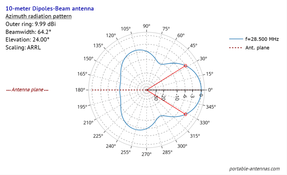
Depending on how high the antenna is deployed, and at what angles its' legs are set at, the "4DX" Dipole beam antenna provides an azimuthal -3dB beam-width of about 65° and a F/B ratio of 12dB or better:
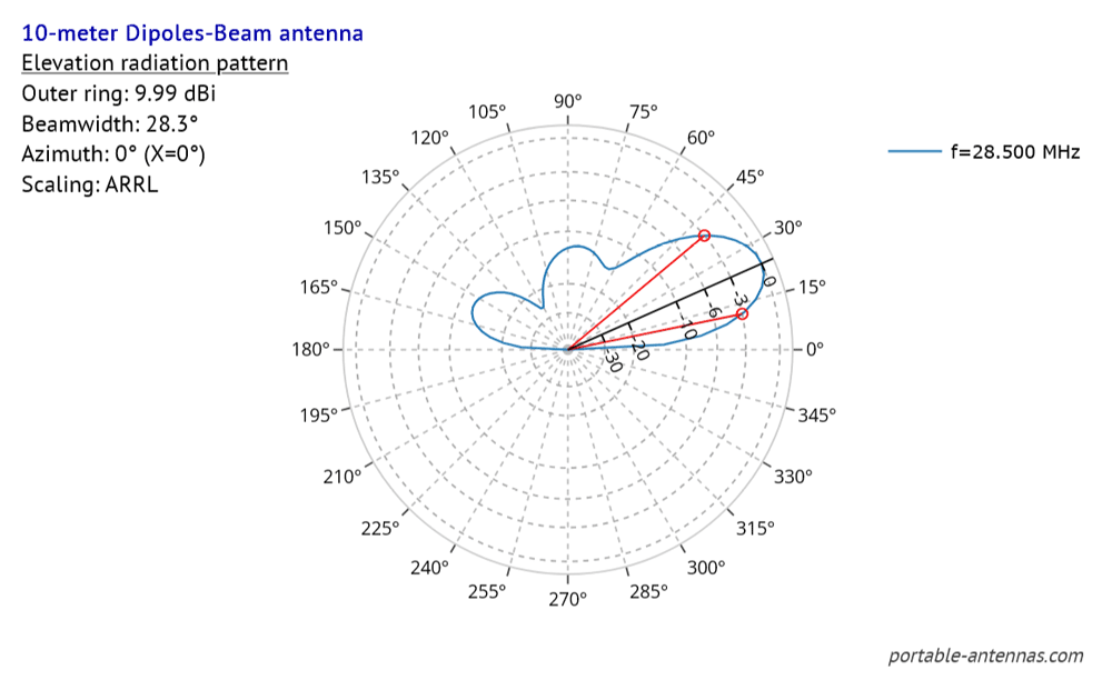
The elevation radiation pattern has a -3dB beam-width of 28° to 30° with its' main lobe peaking at between 24° to 27° :
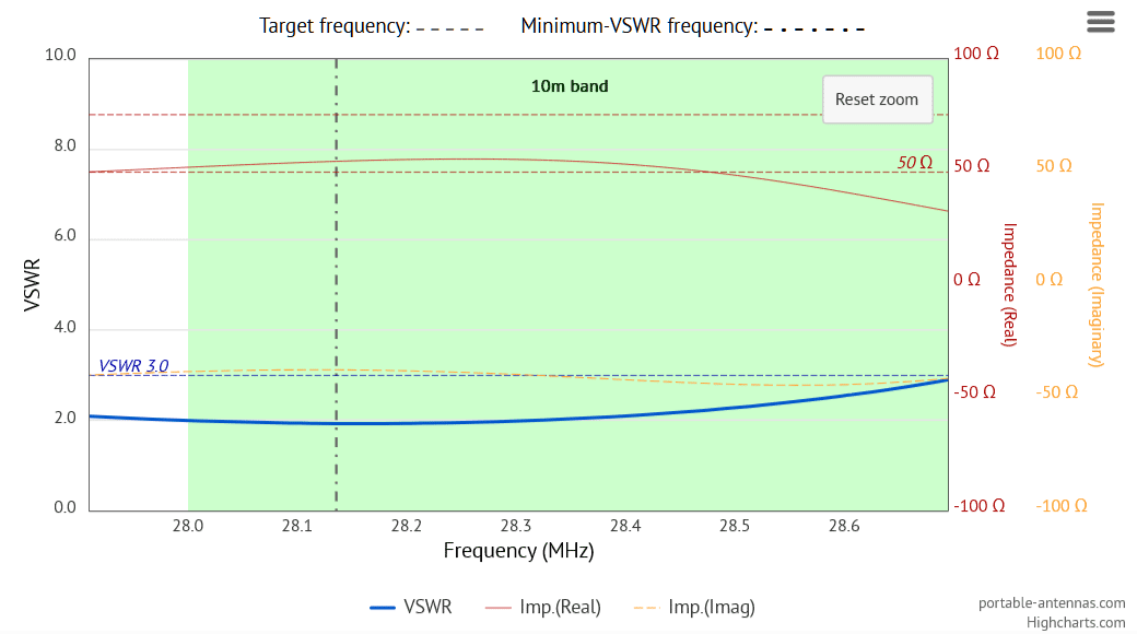
The VSWR curve shows a fairly flat 2.0:1 bandwidth of about 300 kHz:
The antenna can be made multi-band, either by introducing physical links in the antenna legs (as a double linked dipole), or by introducing traps in the antenna legs.
With the ability to change beam direction literally at the flip of a switch, the "4DX" Dipole beam antenna can be a very useful antenna for activations of parks, islands/lighthouses, and for outdoor competitions or for Field Day activations.
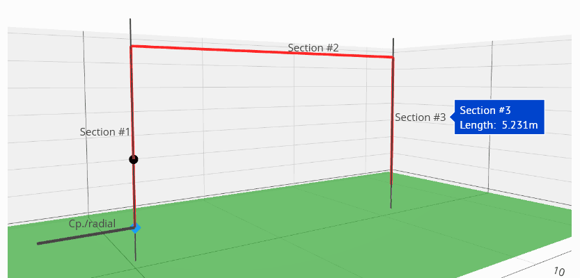
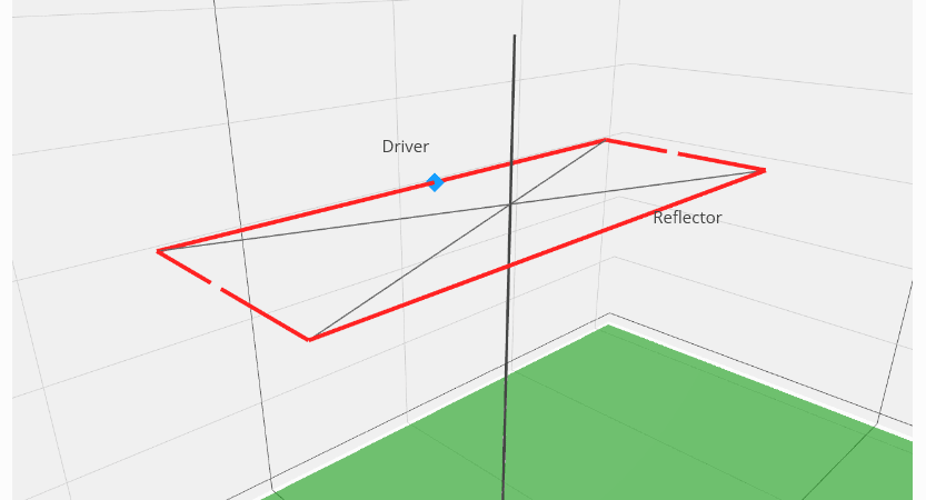
Hentenna antenna designer
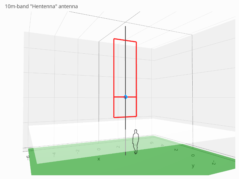
The Hentenna antenna designer page enables the user to quickly design a "Hentenna" - a compact lightweight wire beam antenna for portable use in the field, or on a mountain top. This type of antenna needs a single support only, has a low elevation take-off angle, and is a good choice for single-band DX. If the antenna is supported only by a vertical pole, the beam direction can be changed simply by rotating the pole by hand.
The "Hentenna" antenna - sometimes known as the "Japanese miracle" - was originally developed by a group of Japanese 6-meter operators in the 1970s - the "Hen" (meaning interesting, unusual, strange, etc.) in "Hentenna" was chosen to reflect the curious fact that, when vertically- oriented, the antenna has horizontal polarization, and vice-versa.
Performance
The antenna's feed-point impedance is generally 60 to 65 ohms, so a fair match to a 50 ohm system. The azimuthal radiation pattern resembles that of a dipole in free space, with two lobes firing perpendicular to the plane of the antenna; half-power (-3dB) beam-width is approximately 90°:

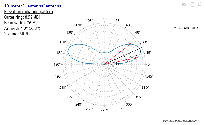
In elevation, the radiation pattern consists of a single low-angle lobe at 24° or 25°, with a half-power (-3dB) beam-width of about 27°:
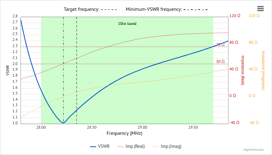
The VSWR curve is symmetrical, and presents a 2:1 bandwidth of over 600kHz on 10 meters: