portable antennas
Welcome to portable-antennas.com! - a collection of easy-to-use tools developed by a radio amateur (read more) for use by anybody with an interest in designing and building their own lightweight portable wire antennas for the HF amateur bands.
Such antennas are primarily to be used in person-portable / rucksack-portable activations of parks, hills and mountains, islands and lighthouses in the various amateur radio outdoor award schemes. They would also be ideal for Field-Day operations, either as the main antenna for a single-op entry, or as an alternative antenna for multi-op entries. Of course, the same antenna designs can also be used at a home QTH - just use more substantial fittings and support structures.
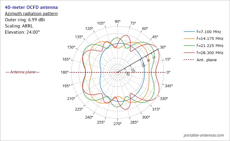
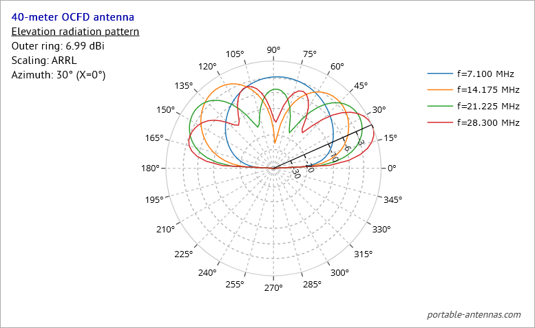
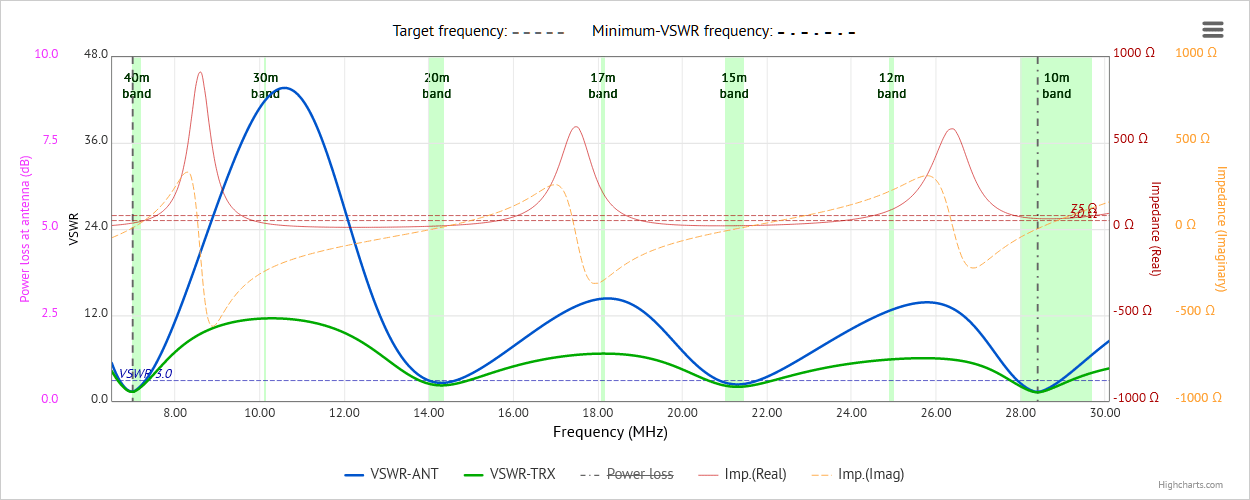
The tools included in each designer page enable displays of radiation patterns, VSWR curves, antenna current diagrams, and Smith charts - all calculated and displayed dynamically for the antenna you design. No other website offers such an extensive set of tools to check your antenna design.

Example azimuth radiation pattern
|

Example elevation radiation pattern
|
Power to the user
The designer pages in this site use the powerful industry-standard NEC engine in the background to dynamically calculate data describing the performance of the antenna you have designed. These data are then parsed, analyzed and displayed in the formats you have chosen. Up until recently, we had been using an older NEC v2 engine in the background, but we have now updated all of the designers to use a more up-to-date and more capable NEC v4.2 engine, under license to us for your use.
Of course, other NEC-based antenna modelling and design tools and programs do exist: for instance: EZNEC Pro, 4Nec2, MMANA-GAL * and others, but all of them need to be installed on your PC or Mac/Linux machine. These programs are certainly very powerful, and generally give very good results - the downside is that such programs are often very complex, and involve a steep learning curve in order to become proficient in even the simplest of tasks. Not everyone has the desire to spend so much time and effort in gaining the skills and knowledge required by such programs to model even the simplest kind of antenna.
* We accept no liability for the content of external links - use them at your discretion.
Easy to use
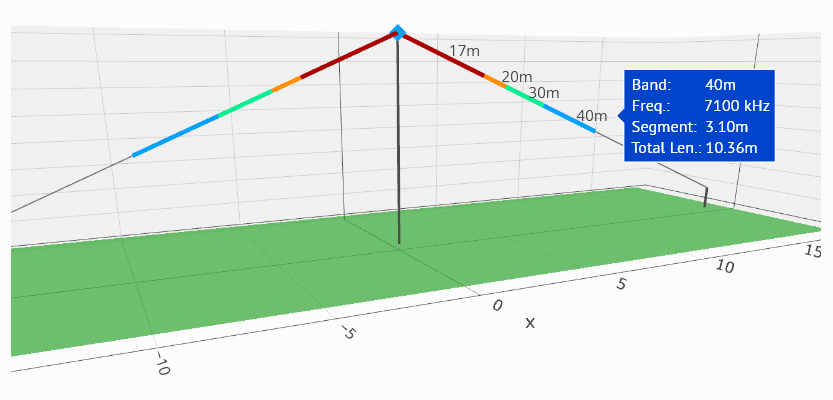
The tools provided in this site take much of the complexity out from the task of modelling and designing of simple wire antennas. Parameters such as frequency, wire lengths and angles are easily input, and results presented in interactive 3D graphical form at the click of a button.
This is achieved by having each of the designer pages in this site focus on one particular type of antenna, with custom code and options to match, making it much easier for the user to concentrate just on the antenna of their choice. This is quite unlike the approach taken by the programs mentioned earlier because, since they are designed to cater for any and all conceivable antenna types, the large number and scope of options they need to include can quickly become confusing or bewildering.

Experiment!
Users of the antenna designer pages in this site are encouraged to experiment with the antenna designer of their choice, to try different values of frequency, antenna section lengths or angles, height of antenna above the ground, to try out different ground types, and so on. Spend some time to see what effects these changes will have on the antenna's radiation patterns, or on the VSWR, or how currents are distributed in the antenna, as the changes are made. In this way, you will learn a great deal more about your choice of antenna in particular, and also about antennas in general, than just trying one set of values.
Different antenna types
Currently, the following antenna types for the HF bands can be modelled, with more being considered for inclusion:
- Linked dipole antennas - for single or multiple HF bands;
- Off-center-fed dipole (OCFD) antennas - capable of giving good results on several bands above the principal band;
-
End-fed half-wave (EFHW) and end-fed random-length (EFRL) antennas
- EFHW - capable of giving good results on several harmonically-related bands above the principal band;
- EFRL - capable of giving good results on several bands above the principal band, including WARC bands;
-
Vertical antennas
- for one single band, with all-round, low-angle radiation;
- NEW - now includes a loading coil calculator to enable shortened 1/4-wave verticals to be designed;
- Delta loop antennas - for a single band, providing a choice of polarization directions at low elevation angles - a good DX antenna.
- Half-square antennas - can be configured either as a full-wave single-bander, or as an EFHW multi-bander.
- Moxon antennas - for one single-band, a compact two-element beam antenna with good gain and very good F/B ratio.
A couple of "custom" antenna designers have also been developed,
for more specialized antenna types. These antennas are being used
in portable activations contexts,
but they're generally not as well-known or as popular as the more "standard" types listed above:
- "4DX" Dipoles-beam antennas - switchable, directional dipoles-beam antenna for one or more HF bands;
- "Hentenna" antennas - compact double-loop antenna with good DX properties, well-suited for portable use
-
"LoG" RX antennas
- A "Loop on Ground" receiving antenna most suited to low bands use - not perhaps everybody's choice
as an antenna for portable use, but it might be used as a receive antenna in combination with a more conventional antenna for
transmitting, especially for the lower HF bands. In light of its' good SNR figures, it may be worth trying this out!
Radiation patterns, polarization patterns, VSWR charts, antenna currents diagrams and Smith charts
For each of the antenna types currently supported, any combinations of the following charts and diagrams can be generated and displayed:
- azimuth and elevation radiation patterns;
- 3D radiation patterns;
- azimuthal polarization patterns, showing both horizontal and vertical components of the polarization pattern, as well as their sum;
-
VSWR curves, incorporating real and imaginary impedance curves - VSWR curves are displayed for
either one single band, or over several bands; - antenna currents diagrams, showing how currents are distributed in the antenna;
- Smith charts, showing how antenna reactance changes with frequency.

Export results
Results from the design and modelling can be exported in PDF format. In addition, antenna dimensions suitable for importing into a professional program can also be exported.
Extras pages
In addition to the antenna designer pages, the site also offers a palette of Extras, arranged as separate groups of tab-pages, each group presenting a range of related topics:
-
Extras - coax data and charts
- data-sets and charts for over 20 coaxial cable types suitable for portable operations
- a chart of additional line losses due to SWR
- a chart of SWR at the transmitter plotted against SWR at the antenna, for various loss figures
- a discussion on how we calculate losses, due to a transmission line, in VSWR charts
-
Extras - calculators
- a frequency to wavelength calculator
- a calculator to convert a VSWR value to mismatch loss, percentage power lost, etc.
- a Metric to Imperial units calculator
- a calculator to convert reactance value to inductance or capacitance value
- a calculator to add or subtract decibel values
- a calculator to find the matching impedance of a quarter-wave line matching transformer
-
a table to aid in estimating the amount by which the length of a newly-constructed wire antenna
should be adjusted, in order to achieve resonance at the design frequency -
a configurable chart with which you can estimate an optimal length for an end-fed
random-length (EFRL) wire antenna, based on wire type + insulation, and bands of interest
-
Extras - reference
-
interactive animated standing-wave charts. Use controls to generate
animated standing-
wave charts for any VSWR value of your choice. - tables and charts of reference correction factors used in the designer pages
- charts of length-correction factors for various types and/or thicknesses of wire insulation
-
interactive animated standing-wave charts. Use controls to generate
animated standing-
Support pages
The site also offers the following support pages:
-
Antenna types support, information and help
- an overview of the main designer pages in the site, and includes descriptions of the
antenna design pages, with some introductory information on each antenna type and its' characteristics. - Radiation patterns overview - giving an overview of how radiation patterns are generated, and how they relate to each other.
- General site information - an overview of some aspects of the designer pages in the site.
About page / Contact form
The site also offers the
-
About page
- which gives an overview of the main pages in the site, and includes descriptions of the antenna design pages, with some
introductory information on each antenna type and its' characteristics. - Contact form - use this to report errors, request new features, or just to tell us how much you like this site!
Footnote
Please be aware that this site is a work in progress, with updates occurring on almost a daily basis. From time to time, some functions
may not appear to work, or may not work correctly. This simply means that those functions are in the process of being updated or
changed. If it doesn't work now, check back later!
If any problems with the site should persist,
please use the Contact form to let us know!